Electrician Talk banner

Time delay pump setup... help?

1 reading
13K views 57 replies 16 participants last post by  JRaef  
#1 ·
Okay, here's a scenario I need to get some input on.

I've got a water pump station that draws out of the river with three 40 hp pumps. The station is really old and out of date and is going to be replaced in a few years, but for now, the City wants to get some stuff updated a bit.

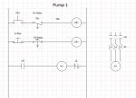
The pump motors are all controlled with across-the-line starters. In order for the pumps to not all start up at the same time and create a surge up the water line, they had someone come in a long time ago and put Delay-on-energize relays in, so that there is an interval of 15 seconds or so between each pump coming on.

Now the problem is that when they shut the pumps off, they all shut off simultaneously, which creates another pressure blast up the line to the nearest surge tank. I recommended that they put in some soft starters at least, but they didn't want to go to the expense. They simply want to add a delay on de-energize feature so that the pumps shut off in a sequence, instead of all at once.

I suggested a PLC but they don't want to go through the trouble when the facility is going to be replaced in a few years. So now I'm stuck trying to figure out a way to do this with timing relays.

Is there a relay out there that can do a DOE and a DODE contact on the same relay for the same output? Would it work to get a DODE relay and just put it in series with the existing DOE relay? How can I ghetto rig this thing up? :thumbup: Oh yeah, the control circuits are straight 480 :blink: No control transformer (although I can add one if necessary).
 
#2 ·
There are specialty timers that are on and off delay, but none of them will be 480V rated, so plan on adding the CPT. You might also look into simple pump controllers from people like Time Mark. The make a low cost simple triplex controller that will do all three pumps and I believe will stagger the starts and stops. But make sure your customer realizes that this surge issue will persist in the event of a power failure, because with electricity the timers do no good. They really should have a hydraulic check valve in those pumps or at least on on the common header. I know the hydraulics is not your problem, but I've had people complain to me that soft starters failed to soft stop their pumps when the power fails! They don't think things through very well before getting themselves worked up. I like to make sure up front that they understand the ramifications and are not stuck in "magical thinking" mode.
 
#4 · (Edited)
#7 ·
erics37 said:
Damn, that timer relay is perfect. Where do y'all find this s**t? :laughing::thumbup:

Thanks for the advice.
Take a look at the site I listed.
I believe the 339 is one of theirs.

Also think about the ARM-120 series. They have the option to "skip" a load during a single pump down for maintenance.
 
#17 ·
Is this drawing right ?
If it were me, I'd put the E-stop between the control relay and motor starter instead of before the control relay. If I understand your drawing correctly, it appears the E-stop might not stop the motor under every condition.
 
#14 ·
No you are very observant and it's not a dumb question. You're right in that most electronic off delay relays need power to the coil constantly and have a separate initiate contact. But the description of this is a "true off delay" which means it mimics the operation of an old pneumatic or spring wound Off Delay timer in that the off delay begins when power is removed from 2 or 7. It's harder to do with electronic timers, that's why you don't see it much, but I like it that way because I think it's simpler. What they do is use a super capacitor inside that maintains power to the electronics for the duration of the off delay setting and still maintains enough juice to operate the contacts at the end.
 
#19 ·
Is there a reference for that statement? I'm not saying your wrong, just never heard it put quite that way and was wondering if it's a code you read or it's "we've always done it that way" or it's your opinion, or someone taught it to you that way.

Thanks,
 
#23 ·
Kind of a pointless argument, that drawing is unworkable anyway (aside from mis-labeled).

But anyway, E-stops should be wired in way that is, with as little room for error as possible, going to positively cause power to stop flowing in a circuit. The more relays and such between the E-stop and the power devices, the more chances there are for something to go wrong. But there are no hard and fast rules for this, there is in fact no absolute requirement for an E-stop at all.
 
#27 ·
Will it work ?
That looks like the basic idea. Now the problem is that the motor controls are currently all 480 volt. The timing relays are only good for 120 volts. So you need to work 480 v to 120 v control transformer(s) in there and either (a) Find a timing relay with contacts rated for at least 480 volts to switch the actual coil circuit, or (b) Change the starter coils out to 120 volt ones.

Whichever method is cheaper.
 
#33 ·
JRaef, thanks for all that info,

1) I didn't think you needed a seal in circuit, or low voltage protection (3 wire control) because who cares if they start back up after a power failure.
2) Independant control - Good point !
3) Yes C1 is my coil
4) I used that relay you showed that has both built in, I didn't know how to separate the control to them.
5) Improvments- I should have a 3 separate start/stop buttons, or just a run switch. One for each pump for independant control.
6) 2 wire control is what I thought I used, with no seal in circuit.
7) control timers on delay, and off delays separately
 
#47 · (Edited)
Here is a drawing that will allow all three pumps to alternate start and stop. Since each pump will require it's own sequence, it will require 3 electronic timers like shown in the post above.
CR1 is used to initiate the cycle. As in every individual drawing, there can be other ways to do this. I am practicing with the new drawing software. I hope this turns out okay.
Here is your drawing Eric.

Well the drawing is fine. The file sucks and cannot be read. I will try and fix it and edit it. Sorry.
 

Attachments

#49 ·
Yes, In my diagram the seal in circuit (latch) is required to keep power on all three timers and on CR1, until the stop button is pushed. We could have used one of the timers contacts to hold the circuit energized. But for simplicity I used a relay.
Also, if the timing relay (above) has a hold power (latch) function internally we would not need a relay at all. I assume this timer works as others and does require a latch to remain energized.

Yes, If the power is lost the pumps sit idle until someone physically pushes the start button. Keep in mind, this drawing is designed to work with the dual on/off delay timer discussed above. If we were using standard electronic timers this drawing will not work. It would only work for either on delay or off delay. Using the timer above, we can delay both "on" and "off" in one timing relay.
I did not consider power loss, nor have we been told what initiates operation of these pumps. Do we have float switches? Do we have level control? You can see my drawing is of the most basic form. From this drawing we can add remove and edit anything we like. We become authors in a sense.
I will work on a power loss scenario and post back along with checking Dorian's drawing on post #30.

Dorian. I did not edit the drawing in "ms.paint". I think I know how to do it from there. But I do have issues with not being able to save these prints, documents in standard fashion. Screen print from paint will not be enough should we decide to edit drawings together.
 
#50 ·
John, Add HOA, in case they want to overide th TD, and run the pumps separate.

I thought the Latch circuit was just for Low Voltage Protection, for safety reasons. I used just a Run switch, which would just restart unmaned, if there was an outage.

I don't think there are any floats in the tanks. Just moving fluids, or water.
 
#53 ·
John, Add HOA, in case they want to overide th TD, and run the pumps separate.
I thought the Latch circuit was just for Low Voltage Protection, for safety reasons. I used just a Run switch, which would just restart unmaned, if there was an outage.
I don't think there are any floats in the tanks. Just moving fluids, or water.
Whats the system for numbering wires ?
Thats right. You can add the HOA to override the control scheme. But we should give each pump it's own start/stop circuit then. If we want total control of this circuit we want to be able to control each pump separately. ( I would encourage this ). This is what we are missing in this equation. We have no instructions. We do not know what is expected from this system. I like to call this the "scope of operation".
When anyone asked for a machine to do the things they want it to do, I ask them to write it down. Step by step. This is how we design the schematic. To meet the requirements written for us. In most every case we are asked for input? We can advise, but the operation needs to be known to all parties, verified and signed off on, in some cases.
In Eric's situation we know very little. We know 3 pumps exist. We know they want them to stagger on and off. But other than that we know very little.
Is there some remote control required. Power loss? Auto restart? Things like that.

The latching part of the circuit is used for all three wire circuits unless we want momentary operation of all devices. If we want a pump to stay running, we must latch the circuit closed once the pump contactor is closed. You understand that.
Circuits in PLC and drive work allow for programming of control principle. 2 wire, 3 wire, pump control, ect......
In a case like this, you design your circuit as to the programming choice. For an example in a two wire circuit, the need for a latching circuit is not required. Like a light switch in your room. It is a 2 wire circuit. If you added a momentary push button it would require a 3 wire circuit to work. Something must hold/keep power to the fixture, otherwise it shuts off.

Numbering wires is part of your responsibility when designing a schematic diagram. Notice I numbered the wires on my drawing? I did this without thought. It came second nature. I cannot build this system without wire numbers. When I physically install that wire, I check it off. That way I can keep up with the many wires in a control scheme. I also want the end user to know what wire goes where and what it does. Without numbers this is not possible.
You control what numbers are used. Just make sure you use numbers on each and every single wire.
I like to use #2 for the white or colored grounded conductor and #1 coming from the control transformer. Then start with #3 and keep going.
If you only had a book with numbers 100-200, then use 100-200. Just use them.

Thanks...............John